High-voltage DC lunar cable
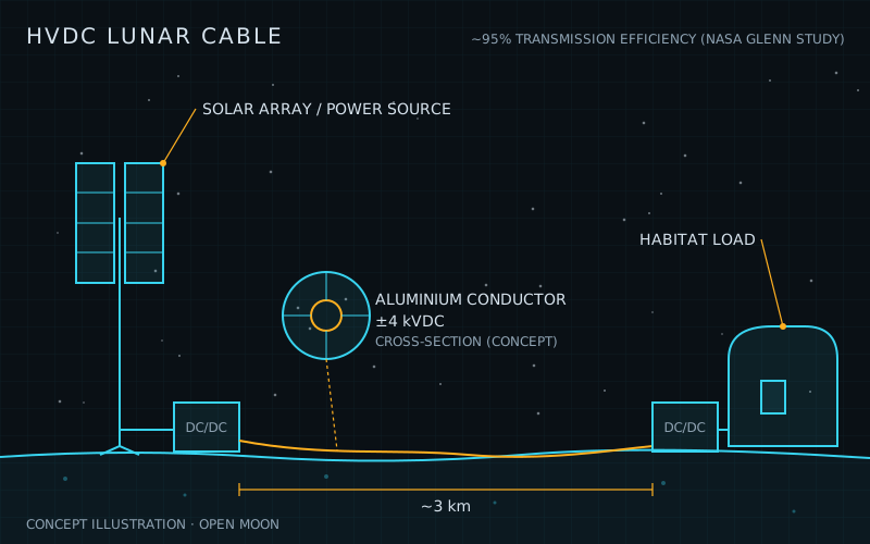
NASA Glenn analysis: ±4 kVDC Al cable best for 3 km at 95%
What it is
A high-voltage DC lunar cable is an insulated metal power line laid on the Moon’s surface. It carries electricity from a power plant to users a few kilometres away. Raising the voltage cuts the current, so a thinner and lighter conductor can carry the same power. On Earth the same idea is called high-voltage direct current (HVDC).
The design Open Moon follows comes from NASA Glenn Research Center. In 2022 Christopher Barth and David Pike studied how to move 40 kW from a fission reactor to a base 1 to 3 km away. For a 3 km aluminium cable at 95% efficiency, they found that about ±4,000 VDC (8,000 V line to line) gave the lowest cable mass. A companion NASA reactor concept used ±2,800 VDC over 1 km, with a cable of about 45 kg. The same study found that a 3 km cable would weigh 3,300 kg at 500 V but only 240 kg at 2,800 V. NASA had reached a similar conclusion in 2008, when it recommended DC cabling for moving up to 50 kW across the surface.
No high-voltage DC cable has flown yet. NASA’s own baseline has since moved to AC. A 2022 grid trade study chose 3 kV AC because DC is in practice limited to about 1.2 to 1.5 kV by the lack of radiation-hard switches. NASA’s 2025 fission reference design uses a 3 kVac, 1 kHz link.
Why Open Moon uses it
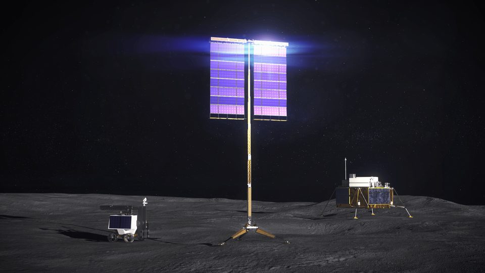
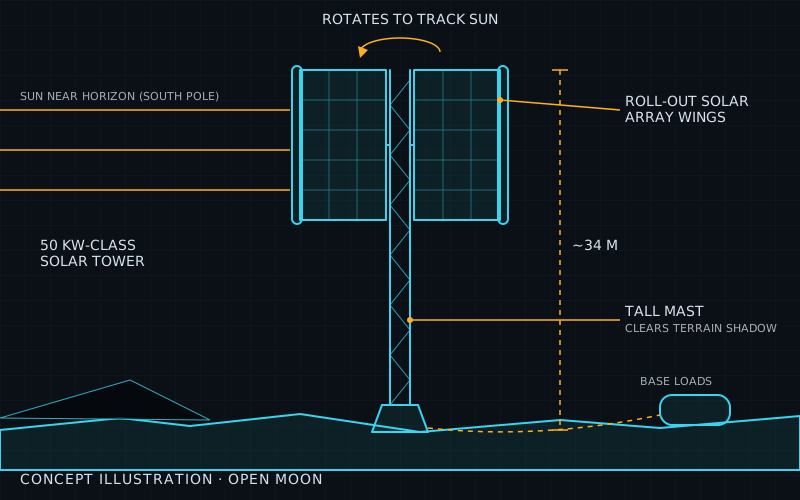
Milestone M04 builds the base’s power grid. It links solar towers, a fission reactor and storage to the oxygen plant and the habitat with ±4 kVDC aluminium cables, 1 to 3 km long. The reactor needs that distance. At 3 km it sits beyond the 2.4 km lunar horizon, which shields the crew from its radiation.
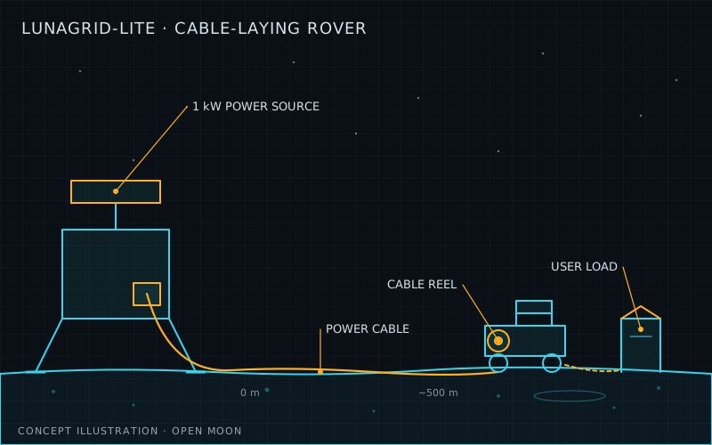
Efficiency matters because fission power is heavy, about 0.25 to 0.27 kg per watt. Every watt lost in the cable has to be made up with extra reactor mass. A 77%-efficient high-voltage line adds about 3,200 kg of generating capacity. Power beaming would add 30,000 to 60,000 kg. Without a cable like this, the base would have to sit next to the reactor or rely on much heavier options. The milestone’s exit criteria also need a rover to lay at least 3 km of cable. Astrobotic’s LunaGrid-Lite is a small first step: it is planned to lay 500 m of cable and carry 1 kW.
How it works
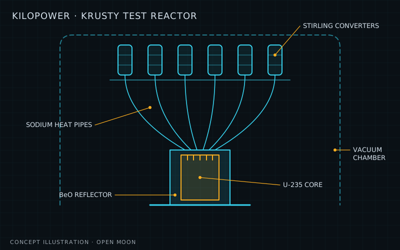
The reactor’s Stirling generators make AC, which is rectified to a 300 to 400 V DC link. A redundant boost converter raises this to transmission voltage. Because space-qualified silicon switches are rated to only 160 V, the converter must stack many small bridges in series. At the far end, a step-down converter brings the voltage back down. In NASA’s reactor concept it converts to 120 VDC and splits the power into eight 5 kWe feeds.
The cable is a balanced pair (+ and − relative to the lander). Conductor mass falls with the square of voltage, but insulation mass rises with voltage. The best voltage is where the two balance. The conductor was kept at 16 AWG or thicker for strength.
| Parameter | Value | Source |
|---|---|---|
| Power carried | 40 kW | Barth & Pike |
| Distance | 1-3 km | Barth & Pike |
| Mass-optimal voltage (3 km) | ±4,000 VDC | Barth & Pike |
| Cable efficiency (design choice) | 95%, about 0.7 W lost per metre | Barth & Pike |
| Conductor / insulation | Aluminium / FEP, 0.6 mm outer case | Barth & Pike |
| Cable mass, 3 km at 2,800 V | about 240 kg | Oleson et al. |
| End-to-end efficiency (Stirling to user) | about 78% | Oleson et al. |
Limitations and open issues
- Radiation-hard switches. Space-qualified silicon is limited to 160 V. 650 V GaN devices are expected to be derated for radiation. NASA puts the practical DC limit at 1.2 to 1.5 kV, well below ±4 kV.
- Part count. A 1 kV DC system needs about four times as many parts in the power path as an AC one. More parts usually means more failures.
- Step-down converter untested at voltage. The stacked receiving converter has only been shown up to 600 V at Glenn.
- DC breakers. A DC breaker must quench an arc with no natural zero crossing. High-voltage DC breakers are still a research topic.
- Insulation in vacuum. Vacuum-rated high-voltage cables that avoid partial discharge are still being studied. The mass figures include no micrometeoroid shielding or redundant cable.
- Environment testing. NASA has tested AC cables on regolith simulant in vacuum and saw no major losses. We found no comparable published test of a ±4 kV DC cable.
- Laying and burial. NASA advises against burying the cable because regolith conducts heat poorly. A cable on the surface faces rover traffic and thermal cycling. NASA’s first cable-laying demonstration was scoped at 1 km, but Astrobotic’s 2025 design lays 500 m.
- Diverging from NASA. NASA’s current reference uses 3 kVac. If Open Moon keeps ±4 kVDC, it would need its own converter development. Interfacing with an AC NASA reactor would also need an AC-to-DC stage.
| Alternative | How it compares | Status |
|---|---|---|
| 3 kV AC, 1 kHz three-phase transmission (NASA UMIC) | Uses transformers instead of stacked DC-DC converters to raise and lower voltage, so it avoids the shortage of high-voltage radiation-hard switches and needs fewer parts. The cable is somewhat heavier than a DC cable at the same voltage, and an AC grid with no spinning machines is harder to control. | NASA's current lunar grid and 40 kWe fission reference design baseline; a 1 kW UMIC inverter module has been bench tested and cable losses were measured in a dirty thermal-vacuum chamber (2026). |
| Lower-voltage DC tether (500 V to 1.5 kV) | Stays inside the voltage range that radiation-hard parts can handle today and suits light, mobile loads such as rovers. For a 40 kW, 3 km link it needs far more conductor mass than a ±2.8 to ±4 kV line. | NASA's TYMPO project aimed for flight readiness in 2024; Astrobotic's LunaGrid-Lite (1 kW, ~500 m) passed critical design review in Aug 2025. |
| Wireless power beaming (laser, millimetre-wave, microwave) | No cable to lay or damage, and useful for moving or very distant users. For bulk power from a heavy fission plant, its 13-27% end-to-end efficiency would add 30-60 t of extra generating capacity. | Low maturity at power; the best-known demonstration sent 400 W over 330 m at 20% efficiency (US Navy PTROL, 2019). |
| Superconducting cable | Almost lossless and the conductor weighs only a few kg per km, but it needs coolant hoses, cryocoolers and radiators. NASA estimated more than 3 t of support hardware and about 18 kW of cooling power for a 1 km line. | Judged not feasible for the Moon by NASA Glenn (2022). |
| Carbon nanotube (CNT) rope conductor | Very strong, fatigue-resistant and stable over a wide temperature range. Today its conductivity per kilogram is 6-10 times worse than copper, so it is not yet lighter. | Research stage; small samples have beaten copper's specific conductivity but full cables have not. |
- official Barth & Pike, NASA GRC: Lunar power transmission for fission surface power (NETS 2022) (May 2022)
- official Oleson et al.: A deployable 40 kWe lunar fission surface power concept (NETS 2022) (May 2022)
- official Csank & Scott, NASA GRC: Power and energy for the lunar surface (Apr 2022)
- official Thomas et al., NASA GRC: Establishing a lunar surface power grid (Aug 2022)
- paper Thomas et al.: A modular AC to DC interface converter (UMIC) for lunar surface power transmission (AIAA ASCEND) (Oct 2023)
- paper Mason et al.: Key design trades for a near-term lunar fission surface power system (NETS 2025) (May 2025)
- paper Klopp, Thomas & Csank: An experimental study of losses in high voltage AC lunar power cables (SciTech 2026) (Jan 2026)
- official Kerslake, NASA GRC: Lunar surface-to-surface power transfer (STAIF 2008) (Feb 2008)
- official Birchenough & Hervol: Test results from a simulated high-voltage lunar power transmission line (2008)
- paper Yang et al., NASA JPL: A high voltage tethered power system for planetary surface applications (TYMPO) (Mar 2022)
- official NASA: 2023 NASA Tipping Point selections (Astrobotic 1 km cable demonstration) (Jul 2023)
- official Astrobotic: LunaGrid-Lite completes critical design review, flight model underway (Aug 2025)
- wiki Wikipedia: High-voltage direct current (2026)
Summary
| System | Power |
| Phase | 1 |
| Milestones | M04 |
| Readiness | TRL 5 / 9 |
| Plan status | ready to use |
Sources
- NASA NTRS 20220002315: Lunar power transmission for fission surface power (status and facts)
- Reference for the illustration
More sources are on each milestone page that uses this technology.